If you are familiar with switches and VLANs you might know that you require a router if you want to communicate between VLANs. In this lesson, I’ll show you how you can use a router connected to a single switch as a “router on a stick”.
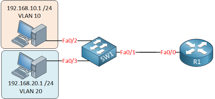
This is the topology we’ll use:
On the switch, we have VLAN 10 and VLAN 20, and there’s only a single cable between the router and the switch. The router needs access to both VLANs, so the link between the router and switch will be a trunk!
It’s possible to create sub-interfaces on a router. These are virtual interfaces, and on each sub-interface, we can configure an IP address, basically, it looks like this:
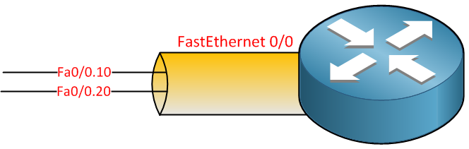
You can pick any number that you like, but I decided to use the VLAN numbers, one sub-interface for VLAN 10 and another for VLAN 20.
Here’s what the configuration looks like on the router:
R1(config)#interface fastEthernet 0/0 R1(config-if)#no shutdown R1(config-if)#exit R1(config)#interface fastEthernet 0/0.10 R1(config-subif)#encapsulation dot1Q 10 R1(config-subif)#ip address 192.168.10.254 255.255.255.0 R1(config-subif)#exit R1(config)#interface fastEthernet 0/0.20 R1(config-subif)#encapsulation dot1Q 20 R1(config-subif)#ip address 192.168.20.254 255.255.255.0Above, you can see my two sub-interfaces and the IP addresses I assigned. IP address 192.168.10.254 will be the default gateway for computers in VLAN 10 and 192.168.20.254 for computers in VLAN 20.
One important command is encapsulation dot1Q . There is no way for our router to know which VLAN belongs to which sub-interface, so we have to use this command. Fa0/0.10 will belong to VLAN 10 and Fa0/0.20 to VLAN 20. Let’s check the routing table:
R1#show ip route Codes: C - connected, S - static, R - RIP, M - mobile, B - BGP D - EIGRP, EX - EIGRP external, O - OSPF, IA - OSPF inter area N1 - OSPF NSSA external type 1, N2 - OSPF NSSA external type 2 E1 - OSPF external type 1, E2 - OSPF external type 2 i - IS-IS, su - IS-IS summary, L1 - IS-IS level-1, L2 - IS-IS level ia - IS-IS inter area, * - candidate default, U - per-user static o - ODR, P - periodic downloaded static route Gateway of last resort is not set C 192.168.10.0/24 is directly connected, FastEthernet0/0.10 C 192.168.20.0/24 is directly connected, FastEthernet0/0.20 You can see both sub-interfaces in the routing table. This allows the router to route between the two VLANs. That’s all there is to it! Configure your computers so that the router’s IP address for the corresponding VLAN is their default gateway, and you are ready to go.
Want to take a look for yourself? Here you will find the final configuration of each device.
hostname R1 ! interface FastEthernet0/0 no ip address duplex auto speed auto ! interface FastEthernet0/0.10 encapsulation dot1Q 10 ip address 192.168.10.254 255.255.255.0 ! interface FastEthernet0/0.20 encapsulation dot1Q 20 ip address 192.168.20.254 255.255.255.0 ! endhostname SW1 ! interface FastEthernet0/1 switchport trunk encapsulation dot1q switchport mode trunk ! interface FastEthernet0/2 switchport access vlan 10 switchport mode access ! interface FastEthernet0/3 switchport access vlan 20 switchport mode access ! endhostname HOST1 ! no ip routing ! interface FastEthernet0/0 ip address 192.168.10.1 255.255.255.0 duplex auto speed auto ! ip default-gateway 192.168.10.254 ! endhostname HOST2 ! no ip routing ! interface FastEthernet0/0 ip address 192.168.20.1 255.255.255.0 duplex auto speed auto ! ip default-gateway 192.168.20.254 ! endI hope you enjoyed this lesson! If you have any more questions, leave a comment below!